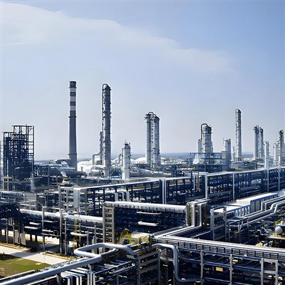
Choosing the wrong shell and tube heat exchanger design can lead to expensive maintenance, unexpected shutdowns, excessive thermal stress, and higher long-term operating costs.
For refinery operators, chemical plant engineers, and EPC contractors, one of the most important decisions is whether to select a fixed tube sheet, floating head, or U-tube heat exchanger.
All three designs transfer heat between two process fluids, but they differ significantly in thermal expansion capability, tube bundle accessibility, cleaning requirements, mechanical complexity, and price.
A fixed tube sheet heat exchanger may offer the lowest initial investment. A floating head design may provide better maintenance accessibility. A U-tube exchanger can accommodate differential thermal expansion without a floating rear-head assembly.
However, the most suitable design depends on the actual process conditions.
This guide compares the three configurations, explains their advantages and limitations, and provides a practical selection checklist for industrial buyers.
What Is the Difference Between Fixed Tube Sheet, Floating Head and U-Tube Heat Exchangers?
The primary difference is how the tube bundle is supported and how it accommodates thermal expansion.

Fixed Tube Sheet Heat Exchanger
Both ends of the straight tubes are attached to tubesheets fixed to the shell. This creates a relatively simple construction, but limits shell-side mechanical cleaning and requires careful thermal-expansion assessment.

Floating Head Heat Exchanger
One tubesheet is fixed while the other end can move relative to the shell. This accommodates differential expansion and, in common removable-bundle designs, allows maintenance access to both sides.
U-Tube Heat Exchanger
Tubes bend back toward a single tubesheet. The U-bends accommodate thermal expansion, and the bundle is normally removable, but mechanical cleaning inside the bends is more difficult.
Quick comparison table
|
Feature |
Fixed Tube Sheet |
Floating Head |
U-Tube |
|---|---|---|---|
|
Tube Configuration |
Straight |
Straight |
U-shaped |
|
Thermal Expansion |
Requires stress assessment; expansion joint may be needed |
Accommodated by floating end |
Accommodated by U-bends |
|
Removable Bundle |
Normally No |
Yes, depending on configuration |
Normally Yes |
|
Tube-Side Mechanical Cleaning |
Good straight-through access |
Good straight-through access |
Restricted at bends |
|
Shell-Side Mechanical Cleaning |
Limited |
Accessible after bundle removal |
Accessible after bundle removal |
|
Mechanical Complexity |
Relatively Low |
High |
Moderate |
|
Relative Initial Cost |
Often Lower |
Often Higher |
Often Between the Other Two |
|
Common Selection Driver |
Simplicity and economy |
Maintenance accessibility |
Thermal flexibility |
These differences are consistent with commonly described TEMA rear-head arrangements, although detailed cleaning access depends on tube pitch, head construction and the specified configuration.
ScienceDirect Topics+1
Fixed Tube Sheet Heat Exchanger: Advantages and Limitations
A fixed tube sheet heat exchanger uses straight tubes connected to tubesheets that are secured to the shell.
Because the tube bundle is not normally removable, the construction can be mechanically simpler than a floating head design.
Main advantages
Lower initial equipment cost
Fixed tube sheet exchangers often require fewer complex mechanical components, making them economically attractive for suitable services.
Straight tube cleaning access
The tube interiors can generally be mechanically cleaned after the appropriate channel covers or heads are removed.
Relatively simple construction
Fewer complex rear-head components can simplify fabrication and some maintenance activities.
Main limitations
Restricted shell-side cleaning
Because the bundle is fixed inside the shell, mechanical access to the outside surfaces of the tubes is limited.
This can be a serious disadvantage when the shell-side fluid produces hard deposits or requires frequent cleaning.
Differential thermal expansion
The shell and tubes may operate at different temperatures and expand by different amounts.
Because the tubesheets restrain relative movement, thermal stresses can develop.
An expansion joint may be required in some designs, but it introduces additional mechanical and maintenance considerations.
When should you choose a fixed tube sheet heat exchanger?
Consider this design when the shell-side fluid is relatively clean, the differential thermal expansion is manageable, tube-side cleaning is practical, and initial cost is an important consideration.
Avoid selecting it solely because it is the cheapest quotation. If the shell side requires frequent mechanical cleaning, a non-removable bundle can increase downtime and maintenance costs.
Floating Head Heat Exchanger: Is It Worth the Higher Price?
A floating head heat exchanger is designed to accommodate differential expansion while allowing removal of the tube bundle in common configurations.
One end of the tube bundle is fixed, while the rear end is allowed to move relative to the shell.
This makes floating head exchangers attractive for demanding refinery and chemical processing applications.
Main advantages
Better access for cleaning
The removable bundle allows access to the tube exteriors.
Because the tubes are straight, their interiors can also be mechanically cleaned, subject to the selected channel and tube arrangement.
Accommodation of differential expansion
The floating end allows relative movement between the shell and tube bundle.
Useful for fouling services
Where both sides may require cleaning, the maintenance advantages can justify additional equipment complexity.
Main limitations
Higher manufacturing complexity
Floating head arrangements typically require additional components, sealing interfaces, and fabrication work.
More demanding maintenance
The floating-head assembly and its sealing components require appropriate inspection and maintenance.
Higher initial investment
A floating head exchanger may cost more than a simpler fixed tube sheet design for comparable service.
When is a floating head heat exchanger the better choice?
It is worth considering when the shell side is prone to fouling, tube-side mechanical cleaning is also necessary, and significant differential thermal expansion must be accommodated.
However, buyers should specify the exact rear-head configuration. Not all floating head designs provide identical maintenance access or sealing arrangements.
U-Tube Heat Exchanger: Why Is It Used for High Temperature Differences?
A U-tube heat exchanger uses tubes bent into a U-shape, with both tube ends connected to a single tubesheet.
The tube bundle can expand and contract without the same axial restraint found in a conventional fixed tube sheet design.
Main advantages
Thermal expansion flexibility
The U-bends accommodate differential expansion between the tubes and shell.
Removable tube bundle
The bundle can normally be withdrawn for inspection and shell-side cleaning.
Fewer tubesheets
The single-tubesheet arrangement can reduce some fabrication complexity compared with designs using two tubesheets.
Main limitations
Difficult tube-side cleaning
Straight mechanical cleaning tools cannot pass through the U-bends.
Specialized cleaning methods may be possible, but they must be suitable for the actual deposits and tube geometry.
Tube replacement limitations
Replacing individual U-tubes can be difficult, particularly in the inner rows.
Bend-related design considerations
Tube-bend radius, vibration, erosion, and support requirements must be evaluated for the actual service.
When should you choose a U-tube heat exchanger?
A U-tube exchanger is often worth considering when significant differential expansion is expected, the tube-side fluid is relatively clean or can be cleaned using an appropriate method, and shell-side bundle access is required.
It may be unsuitable when the tube-side fluid produces hard deposits that require frequent straight-through mechanical cleaning.
Thermal Expansion: Which Heat Exchanger Design Performs Better?
Thermal expansion is one of the most important mechanical considerations in shell and tube heat exchanger selection.
When the shell and tubes operate at different temperatures, they may experience different amounts of thermal growth.

This is the unconstrained expansion of the tube under the stated assumptions. It is not the actual relative expansion between the shell and tubes, nor a complete stress calculation.
If the shell expands by a different amount, the difference must be accommodated by the mechanical design.
How the three configurations respond
|
Configuration |
Thermal Expansion Response |
|---|---|
|
Fixed Tube Sheet |
Differential movement is restrained; stresses must be evaluated |
|
Floating Head |
Floating end permits relative movement |
|
U-Tube |
U-bends accommodate tube expansion |
Engineering recommendation: For applications involving large temperature differences or frequent thermal cycling, evaluate thermal stresses before choosing a fixed tube sheet arrangement. Do not use a temperature difference alone as an automatic selection rule.
Cleaning and Maintenance: Which Design Is Easier to Maintain?
Maintenance requirements can have a greater impact on lifecycle cost than the initial equipment price.
The key question is not simply whether a heat exchanger can be cleaned, but which side becomes dirty and what cleaning method is required.
If the tube-side fluid causes fouling
Straight tubes are generally advantageous when deposits must be removed using mechanical rods or brushes.
Fixed tube sheet and floating head exchangers can provide this access.
U-tube exchangers require special consideration because the bends restrict straight-through cleaning.
If the shell-side fluid causes fouling
A removable bundle is often advantageous because it provides access to the outside tube surfaces.
Floating head and U-tube designs can offer this benefit.
However, the tube pitch and bundle arrangement must also permit the intended cleaning method. For example, a tightly packed triangular tube layout may restrict mechanical access even after bundle removal.
Maintenance comparison
|
Maintenance Requirement |
Preferred Design to Evaluate |
|---|---|
|
Frequent straight-through tube cleaning |
Fixed Tube Sheet or Floating Head |
|
Frequent shell-side mechanical cleaning |
Floating Head or U-Tube |
|
Cleaning required on both sides |
Floating Head |
|
Significant differential expansion with relatively clean tube side |
U-Tube or Floating Head |
|
Clean shell side and simple maintenance requirements |
Fixed Tube Sheet |
These are preliminary selection guidelines, not final engineering decisions.
Which Heat Exchanger Has the Lowest Total Cost?
The lowest purchase price does not always mean the lowest total cost.
For industrial heat exchangers, lifecycle cost can include equipment purchase, installation, cleaning, maintenance, downtime, energy consumption, and replacement parts.
Example: comparing lifecycle costs
Consider a hypothetical project with three technically acceptable exchanger designs.
|
Cost Item |
Fixed Tube Sheet |
Floating Head |
U-Tube |
|---|---|---|---|
|
Initial Equipment Cost |
$40,000 |
$65,000 |
$50,000 |
|
Annual Maintenance Cost |
$7,000 |
$4,000 |
$5,000 |
|
Annual Downtime Cost |
$8,000 |
$3,000 |
$5,000 |
|
10-Year Undiscounted Total |
$190,000 |
$135,000 |
$150,000 |
All prices are hypothetical and provided solely to demonstrate the calculation. They are not Chunlei quotations or market price benchmarks.
This simplified example excludes energy consumption, installation differences, inflation, discounting, and other project-specific costs.
It illustrates why a more expensive exchanger may offer lower lifecycle costs when maintenance accessibility reduces downtime.
For an actual project, compare technically compliant quotations and use the plant's own maintenance and production-cost assumptions.
How to Choose the Right Shell and Tube Heat Exchanger in 6 Steps
Step 1: Identify which fluid is more likely to foul
Determine whether deposits are expected on the tube side, shell side, or both.
Also identify whether the deposits can be removed chemically or require mechanical cleaning.
This can immediately eliminate unsuitable configurations.
Step 2: Evaluate differential thermal expansion
Review shell and tube temperatures under startup, normal operation, maximum duty, shutdown, and relevant upset conditions.
Consider the materials, effective tube length, and expected thermal cycling.
Step 3: Define the cleaning and maintenance strategy
Confirm whether the tube bundle must be removable.
Check whether the plant has sufficient space and lifting facilities for bundle removal.
Step 4: Confirm thermal and hydraulic performance
The exchanger must meet the required heat duty and allowable pressure drop.
Configuration selection should be evaluated together with tube diameter, tube length, baffle arrangement, number of passes, and heat-transfer area.
Step 5: Review materials and mechanical requirements
Select materials suitable for process temperature, pressure, corrosion, and other relevant damage mechanisms.
Confirm the applicable design codes, inspection requirements, and project specifications.
Step 6: Compare lifecycle costs
Evaluate purchase price, installation, cleaning, maintenance, downtime, and expected service requirements.
A more expensive configuration may be justified if it significantly improves maintainability.
Practical Selection Examples for Refinery and Chemical Projects
Example A: Clean cooling service
Project conditions: Relatively clean shell-side service, manageable thermal expansion, and an emphasis on initial cost.
Configuration to evaluate: Fixed tube sheet.
Reason: Mechanical simplicity may provide an economical solution if shell-side cleaning and thermal expansion are not significant concerns.
Example B: Refinery service with shell-side fouling
Project conditions: Frequent shell-side deposits, planned mechanical cleaning, and significant thermal expansion.
Configuration to evaluate: Floating head.
Reason: A removable straight-tube bundle can improve access to both the shell and tube sides.
Example C: High-temperature service with a clean tube-side fluid
Project conditions: Significant differential expansion, relatively clean tube-side fluid, and a requirement for removable-bundle maintenance.
Configuration to evaluate: U-tube.
Reason: U-bends accommodate thermal movement while allowing the bundle to be removed.
These examples are conceptual selection scenarios, not records of completed customer projects.
Common Mistakes When Selecting a Shell and Tube Heat Exchanger
|
Common Mistake |
Potential Consequence |
Recommended Action |
|---|---|---|
|
Choosing only by purchase price |
Higher long-term maintenance costs |
Compare lifecycle costs |
|
Ignoring shell-side fouling |
Difficult or expensive cleaning |
Evaluate removable-bundle designs |
|
Ignoring differential expansion |
Excessive thermal stresses |
Perform mechanical design assessment |
|
Selecting U-tubes for hard tube-side deposits |
Difficult bend cleaning |
Confirm cleaning method before selection |
|
Overlooking bundle removal space |
Maintenance delays |
Check installation and lifting clearance |
|
Comparing incomplete quotations |
Unexpected project costs |
Standardize the RFQ scope |
|
Assuming all floating heads are identical |
Maintenance or sealing complications |
Specify the required TEMA arrangement |
What Should EPC Buyers Include in a Heat Exchanger RFQ?
A detailed request for quotation helps manufacturers select a technically suitable configuration.
|
RFQ Parameter |
Required Information |
|---|---|
|
Heat Duty |
Required thermal capacity |
|
Hot Fluid |
Composition and physical properties |
|
Cold Fluid |
Composition and physical properties |
|
Flow Rate |
Minimum, normal and maximum |
|
Inlet/Outlet Temperature |
Both process sides |
|
Operating Pressure |
Shell and tube sides |
|
Design Pressure/Temperature |
Both process sides |
|
Allowable Pressure Drop |
Shell and tube sides |
|
Fouling Characteristics |
Expected deposits and cleaning requirements |
|
Material Requirements |
Tube, shell and tubesheet materials |
|
Mechanical Configuration |
Fixed Tube Sheet, Floating Head or U-Tube preference |
|
Applicable Standards |
TEMA, ASME and project specifications as applicable |
|
Inspection Requirements |
NDE, pressure testing, documentation |
|
Maintenance Requirements |
Bundle removal, cleaning and access |
|
Delivery Scope |
Equipment, accessories and technical services |
For petroleum and petrochemical projects, applicable standards may include TEMA requirements, ASME pressure-vessel rules, and API 660 where specified. The actual requirements must be confirmed for the project and equipment scope.
Why Choose Chunlei Chemical Machinery for Custom Heat Exchangers?
Chunlei Chemical Machinery provides industrial process equipment solutions for chemical, petrochemical, and refinery-related applications.
For a customized shell and tube heat exchanger project, the equipment selection process should begin with the actual process conditions rather than a standard product designation alone.
Depending on the agreed scope, technical coordination can address:
Heat duty and operating conditions
Fixed tube sheet, floating head and U-tube configuration selection
Tube and shell material requirements
Thermal expansion and mechanical design considerations
Cleaning and maintenance accessibility
Manufacturing and inspection requirements
Technical documentation and delivery coordination
Installation and commissioning interfaces
For EPC contractors and industrial buyers, clearly defining these requirements before manufacturing helps reduce technical uncertainty and procurement risk.